
Components of a Sucker Rod Pump System
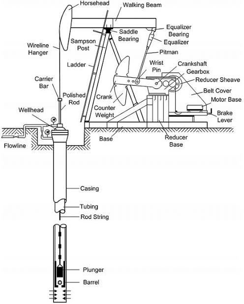
1.Surface Unit (Pump Jack)
This is the most visible part of the system, often referred to as a “nodding donkey” due to its characteristic movement.
It includes a motor, gearbox, and walking beam that converts rotary motion into reciprocating motion.
2.Sucker Rod String
A series of interconnected steel rods that transfer motion from the surface unit to the downhole pump.
These rods are subjected to high tensile and compressive forces during operation.
3.Downhole Pump
Installed at the bottom of the well, usually inside the production tubing.
It consists of a barrel, plunger, valves (standing and traveling valves), and other sealing components.
As the plunger moves up and down, oil is lifted to the surface.
Working Principle of a Sucker Rod Pump
The operation of a sucker rod pump follows a simple cycle:
1.Upstroke:
The surface unit lifts the sucker rod string, moving the plunger upwards.
The traveling valve closes, and the standing valve opens, allowing oil to enter the pump barrel from the reservoir.
Oil trapped above the plunger is lifted towards the surface.
2.Downstroke:
The rod string moves downward, forcing the plunger to descend.
The standing valve closes, and the traveling valve opens, allowing oil to fill the space above the plunger.
This cycle repeats continuously, bringing oil to the surface.
Advantages of Sucker Rod Pumps
Efficiency: Suitable for low-to-medium production rates and depths up to 12,000 feet.
Reliability: Simple mechanical design with fewer failure points compared to other lift methods.
Cost-Effectiveness: Lower operational costs compared to electrical submersible pumps (ESPs) or gas lift systems.
Flexibility: Can operate in wells with a high gas-to-liquid ratio and moderate sand production.