
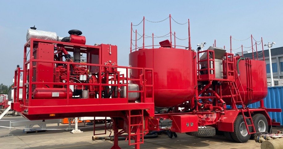
120BBL
Batch Mixer Trailer
Technical Specification
1. General Requirement
a) All the equipment supplied are certified first-hand products.
b) The design specification, manufacturing process and product technical quality of the complete set of equipment shall comply with SY/T 5557-2016 “Complete set of cementing equipment” standard.
c) The control system, instrument box and related devices of all the supplied equipment have good sealing performance, waterproof and seismic ability.
d) All the supplied equipment can adapt to the operating environment temperature of -20 ~ +55 ℃.
e) The layout of all equipment is reasonable to facilitate equipment operation, inspection and maintenance. The equipment on the platform should be equipped with necessary work ladder and warning signs. All exposed moving parts and high-temperature parts have safety protection devices. The various discharge outlets of the equipment point to a safe position.
f) The units of measurement of all instruments and meters of the supplied equipment shall adopt the international metric system (or the international metric system and the imperial system).
g) The equipment has a nighttime construction lighting system, and the lights are not placed at the highest point of the equipment to avoid scratches and damage to the equipment during the form process.
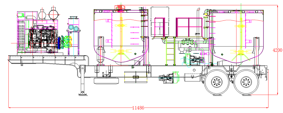
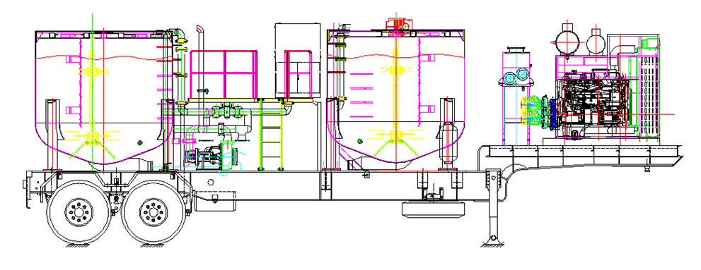
2. Overall Structure and Technical Specifications
Schematic Diagram
2.1 Product Introduction
Batch mixing trailer is mainly composed of trailer chassis, power system, batch mixing tank, manifold system, electrical system, centrifugal pump, hydraulic system, gas system, control system and so on.
Batch trailer is mainly used for batch mixing equipment for cementing operations in desert and land oil fields, and can prepare oilfield cementing slurry with high efficiency and high quality by mixing with agitator.
The equipment takes into account the actual working conditions of the oilfield to form a new product that can be both continuous and batch mixed.
The equipment can meet several working conditions.
Continuous mixing: The mixing slurry can be pumped directly from the mixing tank through the transfer pump to the suction end of the large pump to complete the operation.
Batch mixing: The slurry continuously mixed from the mixing tank passes through two batches of mixing tanks successively to achieve batch mixing storage and continuous cementing operation.
2.2 Performance Parameters and Overall Structure
2.2.1 Performance parameter
| Weight | 23000KG |
| Dimension(ft)(L*W*H) | 11500*2500*4200 |
| Maximum displacement | 3.2 m3/min |
| Density range | 1.0~2.3g/cm3 |
| Mixing capacity | 0.3~2.3 m3/min |
| Batch mixing tank volume | 2×9.6 m3(2X60bbl) |
| Operating temperature | -20ºC~55ºC |
2.2.2 Overall structure
| Component | Specifications | Quantity |
| Trailer chassis | THT9386TD | 1 |
| Engine | QSM11-C360 | 1 |
| Transfer box | STIEBEL 4373 | 1 |
| Batch mixing tank | 9.6 m3 (60 bbl) | 2 |
| Electrical system | 24 V | 1 |
| Centrifugal pump | 6×5×11 | 2 |
| Centrifugal pump | 4×3×13 | 1 |
| Hydraulic system | 1 | |
| Pneumatic system | 1 | |
| Control system | 1 | |
| Manifold system | 1 | |
| Mixing system | 1 | |
| Stirring system | 3 | |
| Spreader | 1 |
3. Trailer Chassis
| No. | Name | Parameters |
| 1 | Brand | THT9386TD |
| 2 | Operating conditions | -20℃~+55℃ |
| 3 | Braking system | Equipped with service brake, parking brake, and emergency braking, and featuring a 4S/2M type ABS anti-lock braking system. |
| 4 | Electrical system | National Standard 24V Trailer Wiring Harness and Lighting Fixtures |
| 5 | Tire | 385/65R22.5-20PR (7 tires), 1 piece spare tire |
| 6 | Gas storage tank | 50L 2 piece |
4. Engine
| Model | QSM11 |
| Power | 268 kW |
| Max. torque | 1,708 N·m |
| Start mode | Electric |
| Cooling method | Fan Radiator |
| Throttle control | Electric |
| Flameout method | Electric |
| Exhaust | Muffler (with Rain-proof Cover) |
| Other configurations | 24 V DC Generator, Thermostat, Air Filter, Rain-proof Cover of the Air Filter, Weather Shield, Turbocharger (Thermal-Protective Coating), Silencer (Thermal-Protective Coating), Exhaust Pipe (Thermal-Protective Coating) |
5. Transfer Case
| Model | STIEBEL 4373 |
| Max. Input Power | 400 kW |
| Max. input speed | 3500rpm |
| Max. power per output port | 210KW |
| Max. output torque per output port | 800 Nm |
| Quantity of output ports | 3 |
| Quantity of input ports | 1 |
6. Electrical System
The power supply of the electronic control system is provided by the battery and the generator of the engine, providing power for instruments, engine start, stop, lighting, etc. The lighting device is easy to operate at night and observe and measure the liquid level inside the tank.
7. Mixing System and Manifold System
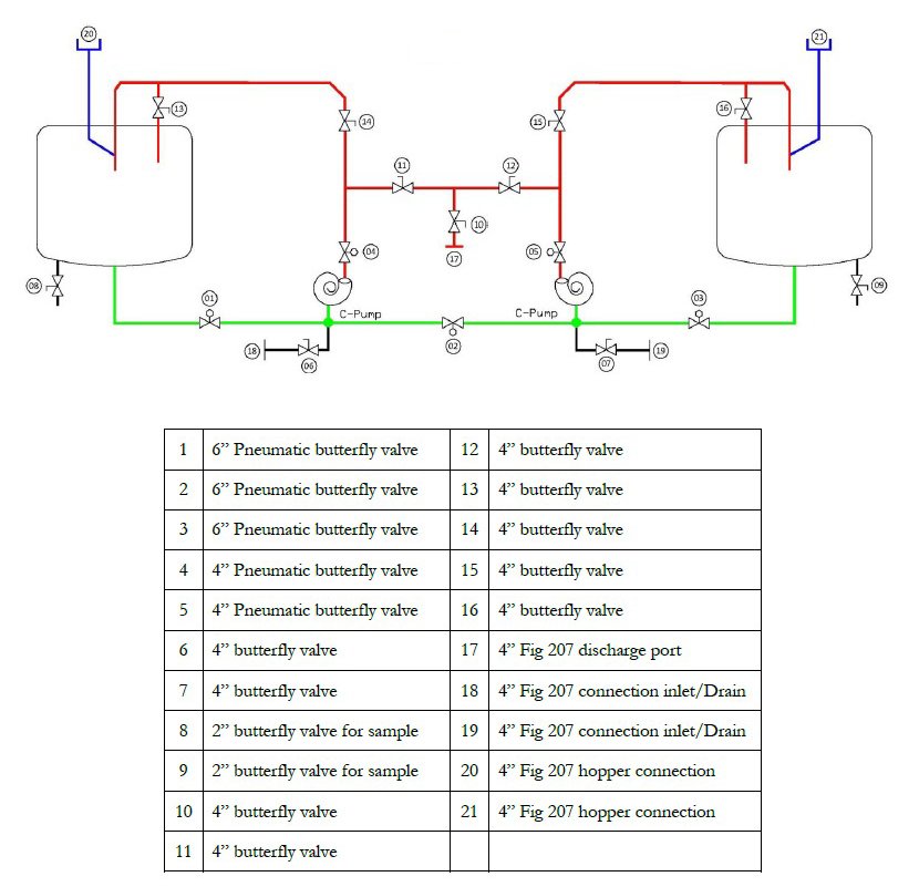
The mixing system is a crucial core component of batch mixing equipment, primarily consisting of a centrifugal pump, jet manifold, mixing tank, mixing pipeline, flow meter, densitometer, simple mixer, and ash supply manifold.
A pressure gauge is installed on the injection manifold to monitor injection pressure.
The suction inlet of the circulation pump is positioned lower than the tank and main pipelines to facilitate the discharge of residual liquid from the tank and pipelines, ensuring a rational pipeline layout and good suction performance.
The injection pump suction inlet is equipped with a 4” connector (FIG206 union type) for connecting to clean water.
The suction manifold at the bottom of the front batch mixing tank (near the engine) is slightly higher than that of the rear batch mixing tank. Viewed from the side of the skid, the entire tank bottom suction manifold is higher at the front and lower at the back, facilitating cleaning and drainage of the entire vehicle. A 4” drain port (FIG206 union head assembly) is located at the lowest point of the rear batch mixing tank manifold.
All rigid pipelines are rationally laid out with smooth transition angles. Connections between pipelines are kept as short as possible and use clamps for easy disassembly and cleaning. The pipeline routing is designed with a certain angle to ensure good suction and discharge performance.
For convenient post-operation cleaning, a 10-meter cleaning pipeline with a high-pressure nozzle is designed into the injection pipeline.
Centrifugal pump parameters:
Model: 6×5
Work speed (r/min): 1750
Max. flow (L/min): 3200 (water)
Pressure (MPa): 0.35
7.2 Injection pump
Model: 4×3×13
Max. speed(r/min): 3500
Work speed(r/min): 2900
Max. flow(L/min): 1600
Work Pressure(MPa): 0.85~1.27
Manifold Process Diagram
8. Batch Mixing Tank
Effective volume of batch mixing tank: 2×9.6 m³ (2x60bbl)
Each batch of mixing tanks is equipped with one high-power mixer, which adopts a double-layer blade structure and has excellent mixing effect, which can prevent the settlement and agglomeration of cement slurry. The tank is equipped with a liquid level gauge, measured in barrels (BBL) and cubic meters (m³) Is the scale.
60BBL batch mixing tank
9. Lubricating System
The centrifugal pump packing lubrication adopts an air top oil lubrication system, and the centrifugal pump packing provides continuous cooling lubricating oil. Main components: lubricating oil tank, pressure reducing valve, switch, needle valve, one-way valve, ball valve, and pipeline.
Lubrication tank capacity:35L 。
Lube:SAE 15W-40
Pressure regulating valve: Reduce the pressure of the air supply system to the pressure required for lubricating the packing, usually 20-30 PSI.
Pressure relief switch: 1/4 “pressure relief ball valve
Pressure gauge: indicates the pressure inside the lubricating oil tank, with an indication range of 0-60 psi
Ball valve: a lubricating oil circuit switch that opens or closes the lubricating oil in this pipeline.
Lubricating oil volume regulating valve: regulates the oil volume of the centrifugal pump packing lubricating oil
Cap and scale: can approximately indicate the level of lubricating oil in the tank
Check valve: prevents mud from entering the lubrication pipeline after leakage of the packing seal.
YWZ-150T。Power end oil tank level indicator: YWZ-150T.
10. Hydraulic System
The engine drives 4 sets of hydraulic pump systems through the transfer box, and the hydraulic pump drives the hydraulic motor, forming 3 independent open hydraulic systems to drive 3 centrifugal pumps, 1 independent open system to drive 2 mixers, and 1 independent open system to control the ash and water inlet valves of the high-energy mixer.
The mixing motor of the batch mixing tank drives the mixer through a reducer.
The hydraulic system is equipped with a hydraulic oil radiator to control the hydraulic oil within the optimal operating temperature range.
Hydraulic pumps, hydraulic motors, remote control valves, and other hydraulic components are all selected from well-known domestic and foreign brands, with safe and reliable quality and performance.
11. Pneumatic system
The air circuit system mainly consists of an air compressor, gas storage cylinders, filtration and pressure reducing valves, pneumatic butterfly valve actuators, and pipelines. The air source is provided by the engine driven air compressor, which mainly controls the opening and closing of the butterfly valve.
12. Control System
The power supply of the electronic control system is provided by the battery and the generator of the engine, providing power for instruments, engine start, stop, lighting, etc. The lighting device is easy to operate at night and observe and measure the liquid level inside the tank.
All hydraulic and pneumatic control units, engine control devices, and butterfly valve pneumatic switches are centralized on the instrument console and its surroundings, making operation convenient. The operation console is made of stainless steel plate, which is beautiful and reliable.
The main components are as follows:
a) Engine start control switch
b) Engine shutdown control switch;
c) Engine throttle control;
d) Display of engine oil pressure and water temperature;
e) Hydraulic control valve;
f) Hydraulic system pressure gauge;
g) Air system pressure gauge;
h) Lighting control switch;
i) Horn control switch;
j) Schematic diagram of the manifold.
13. Painting Treatment
The entire equipment has a beautiful appearance and no obvious spraying defects. The paint spraying meets the anti-corrosion requirements of the land use environment, and the spraying color is subject to the customer’s requirements.