
WHAT IS A 3-PHASE SEPARATOR?
A pressure vessel designed to split a well stream into three distinct phases:
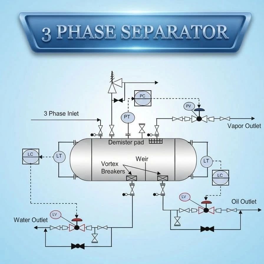
Vapor/Gas → exits top via pressure-controlled outlet
Hydrocarbon Liquid (Oil) → exits via oil weir compartment
Produced Water → exits via water boot or water side
Orientation: Horizontal (most common for high liquid loads) or Vertical (gas-dominant streams)
INTERNAL COMPONENTS — FUNCTION & ENGINEERING BASIS
Inlet Device (Diverter / Cyclonic)
Reduces inlet momentum and distributes flow uniformly
Prevents jetting that disturbs the liquid interface
Types: Half-pipe diverter, vane-type, or cyclonic inlet
Poor inlet design = emulsion formation + poor separation efficiency
Demister Pad
Mesh-type or vane-pack coalescer in the vapor section
Removes entrained liquid droplets from gas (droplets > 10 microns typically)
Design velocity uses the K-factor / Souders-Brown equation:
V = K × √[(ρL − ρG) / ρG]
Plugging risk from wax, scale, or foaming fluids → mandate cleanout access
Weir Plate
Establishes the oil/water interface level mechanically
Height engineered based on oil layer thickness required for retention time
Material: Carbon Steel or SS316L depending on H₂S/CO₂ content
Must account for density variation across all operating conditions
Vortex Breakers
Installed at all liquid outlets (water and oil draw-off nozzles)
Prevents gas core formation (vortexing) during liquid draw-off
Without them: gas blow-by → compressor surge, meter error, control valve erosion
Design per API 12J / GPSA Engineering Data Book
Inlet & Outlet Nozzles
Sized for maximum flow + slug conditions (slug volume from transient analysis)
Nozzle velocity limits: typically < 3 m/s for liquid, < 15 m/s for gas
INSTRUMENTATION & CONTROL LOOPS
Pressure Control Loop:
PT → PC → PCV on gas outlet line
Backpressure regulation maintains vessel at design operating pressure
PCV failure mode: fail-open preferred — prevents overpressure buildup
Water Level Control Loop:
LT (water side) → LC → LCV on water outlet line
Interface detection: Guided Wave Radar (GWR) or Differential Pressure (DP) type
GWR preferred for emulsion-prone or solids-laden service
Oil Level Control Loop:
LT (oil compartment) → LC → LCV on oil outlet line
Oil LCV failure mode: fail-closed — prevents water carry-over into oil export
Interface Level — Critical Challenge:
Oil/water interface measurement is the #1 operational headache in separator control
DP transmitters struggle with emulsion layers due to mixed-density zones
Best practice: GWR + nuclear densitometer combination for high-confidence interface detection
Calibration must always reflect actual fluid densities at operating temperature and pressure